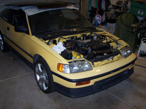
Today was the first day of the yellow CRX turbocharging project. It's an 89 Si Y49, that is almost completely stock. There are a few upgraded suspension components (Tokico Illuminas), and a short shifter. The engine is completely stock, and has never been rebuilt. It has 160,000 miles on it and still pulls the 1/4 at 16 seconds flat (which is what it was rated at when sold new). This car also allowed me finish in second place last year in the Phoenix SCCA NV2 division (1st place was running "R" compound tires).
Not bad for a 16 year old daily driver... but we're going to make it better!
We hope to provide good documentation throughout this project, so that others will have a step by step guide that they can reference when researching for their own DIY turbo project. We also hope to showcase some of our unique products, and document their usefulness when undertaking a project of this nature.
We'll start off with the disassembly of the car. In the interests of good documentation, we will probably be taking off a lot more components than is truly necessary. We will do this so that the pictures will more clearly show the areas of interest.

Hood removed.

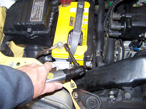
Disconnecting the battery.
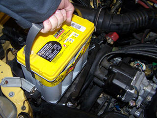
Removing the battery. Still haven't decided at this point if we are going to relocate the battery, or run the charge piping around it. So we'll leave the tray in for now...

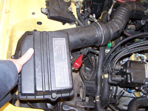
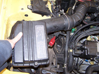
Removal of the stock air intake pieces is next...

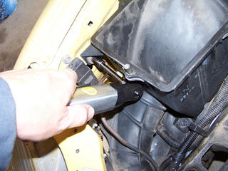
Screws started accumulating, so figured I had better start bagging them up. Didn't have any freezer bags in the garage (shame on me), so snagged some from the house.

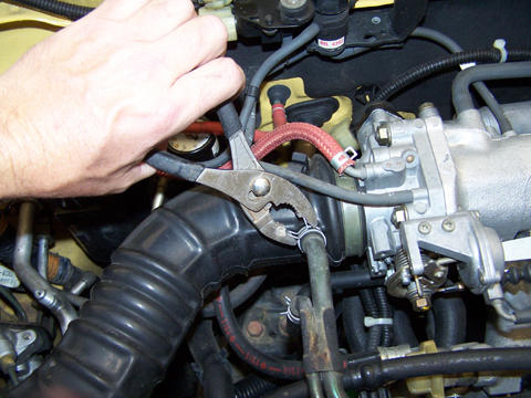
Some more stock air intake pieces come off...

Next off is the cross piece that holds the hood latch. This piece is held in with two screws on each side...

...and one screw hidden down low.

Removal of the front bumper cover starts with these three Phillips screws by the radiator.

This screw in the front air intake.

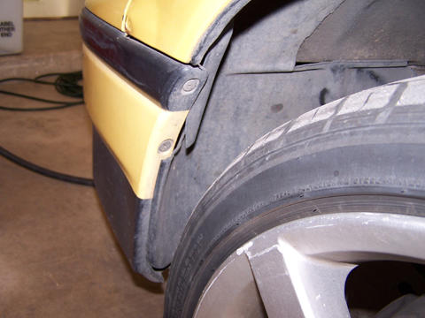
There are two screws hidden on each side of the car, behind the corner light assemblies.

There are two more on each side in the wheel wells.

You may also need to take all of these screws out. The front lip comes off with these.

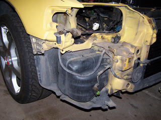
With all screws removed, bagged, and labeled, you can pull the bumper cover out and forward at the wheel wells, and then pull the whole thing off the front of the car. Take the Styrofoam insert out too, and store both in a safe place. The car now looks similar to this...

We are going to pull the headlights too. One of ours needs replacement, and having them out makes for better documentation.

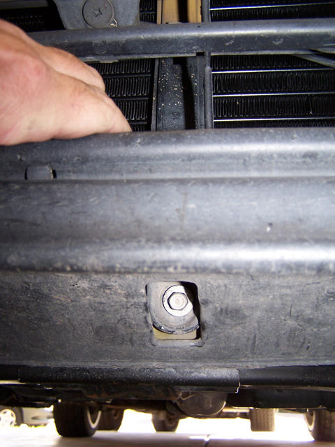
Next is the front bumper. Its fairly easy to do, just remove two screws from each end.

With the bumper out of the way, we can now see another piece of the stock air intake system that will be removed. It's the black tank shown here.
Although this system will be built AC friendly, we are going to remove the A/C components to make things easier to work on. Have your local shop recover any ozone-depleting refrigerants from your system. Our system was already non-functioning, so we popped out a Schrader valve just to make sure there was no pressure in the system. These service ports are back by the firewall.

There is a bolt on each side of the A/C Condenser that must be removed.

And the refrigerant lines must be disconnected.

Hoses and Fans and radiator come out as well. Some of these can be left in, but it is a lot easier to do some of the fab work with them out.

With the condenser, radiator, fans and associated stuff out of the way, you can now get to the stock manifold, and A/C compressor. I put some tape over the ports on the compressor, to reduce the chance of contaminating it.

Underneath, this big bracket reinforces the block to the bell housing, and must come off. The curved bracket holds the stock exhaust and can be removed as well.

A better shot of it. All four fasteners can be removed, and any pieces bagged for later.

Around at the back of the pan, another bracket hold the exhaust in place. This can all be removed too. This picture shows the relation of the bracketry to the oil drain plug.

A better shot of the pipe and the bracket.

The joint that connects the stock downpipe to the catalytic converter. Disconnect it by removing the fasteners from the rearward side of the connection, where the springs are.

Remove the three bolts that hold the down pipe to the stock manifold, and separate them.

What's left hanging under the car, is the factory catalytic converter.

Remove the nuts that hold the stock manifold, and wiggle it off. Keep track of the gasket too.

This is the factory A/C bracket. We're going to take it off for now, for cleaning purposes.

So now we have just about everything removed and can start preparing for the fun stuff. Before that, we'll clean and handle a small issue.

One of the factory exhaust manifold studs is broken, and must be replaced. (It's the unnaturally short one on the bottom-right.)

Here is another shot of the pan area, with that reinforcing bracket that must be removed. It has the three larger bolts in it. You can also see the two mounting studs for the exhaust pipe bracket that came off when we removed the factory pipe.

We are finally taking that reinforcing bracket off.

Our driver's side half-shaft has a blown-out boot. It has coated the surrounding area with a nice mess of axle grease.

Driver's side half-shaft removed from the tranny. You have to disconnect all the associated components from the driver's side hub assembly. Check your manual for instructions on how to do this.

With the reinforcing bracket and the half-shaft out of the way, remove the flywheel cover plate bolts, and pull it down and out.

Flywheel exposed.

Here is what you should see at this point, from under the car. Oil pan is in the top part of this picture, flywheel in the middle, and transmission towards the bottom.

Here is a shot straight up at the bottom of the car. You can see how tight the oil pan is to the flywheel. There are two nuts tucked up in there you'll need to remove when you take the pan off.

The stock bracket for the exhaust gets in the way of an oil pan fastener. You can push it back to get the fastener off. Remove the oil pan. (You did drain the oil first, right?)

Now we get to install so of our new parts. First is an oil feed line from our
Stealthmode Performance Oil Line Kit. The Stealthmode kit has everything you need to connect your turbo into your engine's oiling system.
A shot of the stock oil filter location. This is between the firewall and the engine block, taken from underneath. You can see the blown-out boot at the bottom of the picture.

Removing the oil filter allows you to see the stock oil sender unit. Its just above where the oil filter seats. In this photo the sender is directly above the threaded connector for the oil filter. Disconnect the wire, and remove the sending unit.

After removing the stock sender, test fit the
Tuner Toys block fitting. This fitting is available from our website, and is included in the Stealthmode Turbo Oil line Kit. It matches the stock threads in the block. A normal pipe fitting from the local hardware store is not the correct thread for this port, it has the wrong thread pitch and will disturb the threads in the engine block oil port. You may need to clean any old HondaBond from the stock oil port. Use Teflon tape on all pipe threads.

The block fitting has two ports for accessories. We are only using one at this time, so have installed the provided plug into the lower port. If we need to use the port later, we just have to remove the filter to get to it. In the upper port, we have installed the NPT to AN adapter provided in the oil line kit. You can see it sticking up out of the left side of the block fitting.

Here is a closer shot of the oil filter mounting location, the block fitting, and the AN/NPT adapter installed. Note the orientation of the ports on the block fitting.

The next item from the kit to be installed, is the -3 feed line. Route it down from the top of the engine to the block fitting. Be aware of moving parts, rubbing, and crimping. Connect it to the AN/NPT adapter, tighten it firmly, don't crank it down. AN fittings don't need a lot of force to seal, and you can always go tighter later if it seeps.

Next re-install the factory sender into the back of the block fitting. The threads in the block fitting match the threads in the engine block. The side ports on the block fitting are a different thread type. The installation shown is the only acceptable way of installing this fitting. Connect the wire to the sender. (You can see in the photo that we cracked the plastic cover on this connection. It was quite brittle, but appears to still be acceptable electrically.)

That's it for the turbo feed line installation from under the vehicle. We are going to leave the filter off for now, in case we need to get back in there.
Now for some more fun. Let's see how our turbo looks on this baby!
We have had an HF/BMC/14B combination laying around in our shop for some time. We had it mounted on a blown engine to mock up our
Water Line Kits when we developed them. Our water line kits have everything you need to connect your turbo's water coolant jacket to your engine's cooling system. Although our main goal is to develop a log manifold for T3s, we figured it would be neat to see how the HF manifold solution looks. Below is the manifold and a BMC plate.

Here is a shot of the 14B mounted up to the plate. Looks pretty good so far. This turbo is from a Mitsubishi Eclipse, it's a little small for big HP numbers, but is a good turbo for your first turbocharging project.

This is the Mitsubishi Eclipse O2 housing. It's a pretty neat item to have, as it makes the downpipe fabrication easier in some cases, and when coupled with an HF manifold, gives you two O2 ports to make use of. Perfect for tuning with a wideband, while running on your narrow band. I installed some studs in the 14B to make assembly/disassembly easier.

Here you can see that the HF/BMC combination leaves quite a bit of room between the block and the O2 housing. This doesn't appear to be a problem, until I realize that the outlet of the O2 housing is pointed directly at the front cross member.

About half of the exhaust outlet of the O2 housing is blocked buy the front cross-member.

So this means that some part of our current solution cannot be used. Either the HF/BMC has to go, or the O2 housing has to go. Since we are hoping to use the A/C on this car, the obvious choce is to ditch the HF/BMC, in favor of a log manifold. That way we can tuck the turbo back against the block, continue to use the O2 housing, and also offset the turbo to enable the use of the A/C compressor. (At least that is the thinking at this point.)
Here are some other issues that arose with the use of the HF/BMC. We had wanted to use an AN based drain line on this setup, using one of our new
AN Drain Flanges. These flanges have an integrated -10 An fitting right on them. They are perfect for those who want to use an AN connection on their turbo drain line. Pictured is the 44mm version of the flange, which is commonly used on T25s and 14B type turbos.

You can see it in the picture above, but the image is a little dark. Behind the drain flange on the turbo, is one of our AN based
oil pan drain fittings. These drain flanges are mounted with bolts and require no welding, just drill and attach. We installed one on a spare drain pan to see how it fits for this application. Everthing looks okay at this point.

Its not until you put the hose ends on, that you realize that it's not going to work out. We are trying to use "PushFit" -10 drain line, and the fhose ends are just too long. Here you can see that they overlap each other. There is just not enough room to make it happen. The drain line from the
Stealthmode Oil Line Kit doesn't have this problem.

So now that we have decided to ditch the HF/BMC solution. Our next step is to put together a log manifold. We're going to use one of our D Series
Log Manifold Kits to do this. Our kits come with everything you need to assemble your own log mainfold. Available in all mild steel, you can assemble these kits with a MIG welder, and a few fab tools. We even have an add on kit that adds an
external wastegate connection to your manifold. We won't need this for our 14B, but will show you how to install one later with a
Tial Wastegates.
We'd like to make the point that there is absolutely nothing wrong with using an HF manifold and an adapter plate. Both BMC and
Weir Racing make excellent products and they work perfectly for HF type solutions. Our only reason for not using them, is that we want to use A/C, and we wanted to build a log manifold anyway.
We're in the process of building the log, and will update the post soon.